


Ceiling concealed fan coil units (FCUs) are among the most common terminal devices in air-water HVAC systems. They are widely used in office buildings, hotels, hospitals, commercial complexes, and similar applications. An FCU does not generate cooling capacity itself. Instead, chilled water circulates through its coil, and a fan forces indoor air or primary air across the coil surface for sensible and latent heat exchange, thereby achieving cooling and dehumidification. Therefore, FCU selection cannot be based simply on floor area estimation. It should be determined comprehensively based on detailed cooling load calculations, chilled water system parameters, indoor design conditions, airflow, water pressure drop, external static pressure, and control requirements.
This article systematically explains the selection principles and key technical parameters of ceiling concealed FCUs from a professional perspective, aiming to provide actionable technical references for HVAC designers, contractors, facility managers, and procurement personnel.
1. Role of FCUs in HVAC Systems
An FCU is a terminal device in an air-water system. Its cooling capacity comes from a central cooling source, such as a chiller or modular chiller plant, and is delivered to the terminal through chilled water supply and return piping. Typical chilled water supply and return temperatures are 7°C/12°C, or 6°C/12°C and 7°C/13°C, depending on system design. An FCU does not contain a compressor or refrigerant circuit. Therefore, its energy efficiency cannot be evaluated by EER or SEER. The performance indicators of an FCU mainly include:
Rated cooling capacity (sensible capacity + total capacity)
Sensible heat ratio (SHR)
Chilled water flow rate and water pressure drop
Airflow rate (high/medium/low speed)
External static pressure
Noise level
Power consumption per unit airflow
2. Key Factors Affecting FCU Selection
2.1 Indoor Cooling Load Calculation
The core of FCU selection is determining the cooling load of the room or zone, including sensible load and latent load. The cooling load should be calculated by professional load calculation software according to ASHRAE or local standards. Main inputs include:
Envelope heat transfer, including walls, roof, windows, glass type, and shading coefficient
Solar radiation heat gain, including orientation, window-to-wall ratio, and external shading
Occupant heat and moisture gain, including sensible and latent heat
Lighting and equipment heat gain
Outdoor air load, if the system handles outdoor air
Infiltration or door-opening heat gain
Area-based estimation, such as watts per square meter, can only be used for preliminary estimation and cannot replace detailed calculation. In commercial buildings, the sensible heat ratio varies greatly among different rooms, so calculations must be performed separately.
2.2 Room Area and Ceiling Height
Room area affects cooling load, but it is not the only factor. Ceiling height affects air volume, but its impact on cooling load is usually smaller than that of envelope, windows, occupants, and equipment. Unless the ceiling height is exceptionally large, such as in lobbies or atriums, it is generally unnecessary to apply a simple rule such as increasing cooling capacity by 10% for every additional foot. Instead, the actual volume and air change rate should be incorporated into the load calculation.
2.3 Chilled Water Supply and Return Temperature and Flow Rate
FCU cooling capacity decreases as chilled water supply temperature increases, and increases as the supply-return temperature difference increases. During selection, the following must be clearly defined:
Chilled water supply temperature, such as 7°C
Supply-return temperature difference, such as 5°C
Chilled water flow rate, in L/s or m³/h
Water pressure drop, in kPa
System working pressure
The cooling capacity of the same FCU model can differ by more than 20% under different water temperatures. Therefore, selection cannot be based solely on the rated value in the catalog.

2.4 Airflow Rate and External Static Pressure
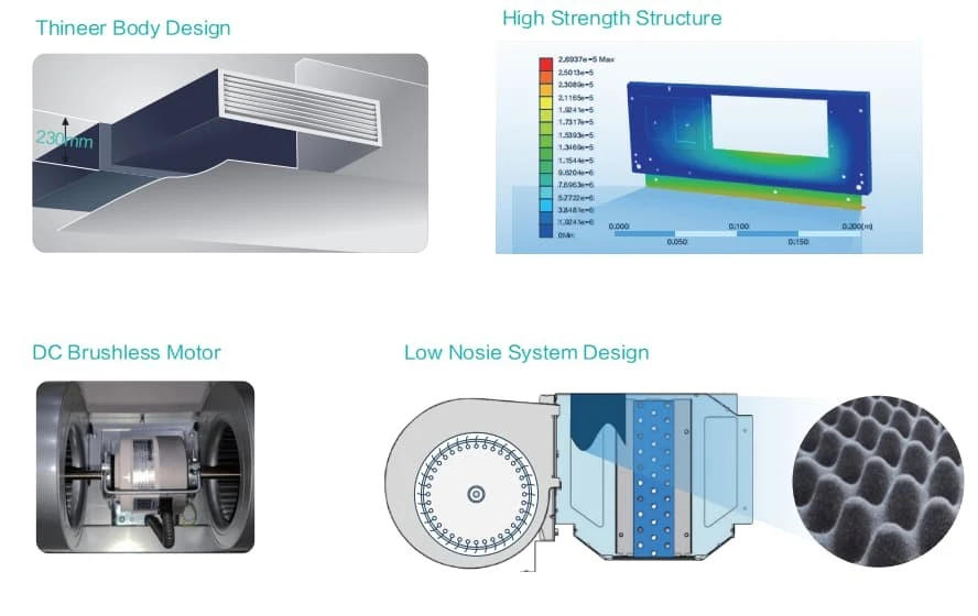
Airflow determines air distribution and temperature uniformity. Ceiling concealed FCUs usually have high, medium, and low fan speeds. During selection, the airflow rate should be determined according to room air distribution requirements, and the external static pressure should be checked to confirm whether it is sufficient to overcome the resistance of supply ducts, return ducts, air outlets, and filters. If the external static pressure is insufficient, the actual airflow will be lower than the rated value, resulting in reduced cooling capacity and uneven temperature distribution.
2.5 Sensible Heat Ratio (SHR)
The sensible heat ratio is the ratio of sensible cooling capacity to total cooling capacity. Different rooms have different SHR values:
Offices and computer rooms: relatively high SHR, 0.85–0.95
Conference rooms, restaurants, and densely occupied areas: relatively low SHR, 0.70–0.85
Hospital wards and laboratories: determined according to process requirements
During selection, the FCU SHR should match the room load SHR. Otherwise, conditions such as "temperature meets the set point but humidity exceeds the limit" or "excessive dehumidification leading to reheating energy consumption" may occur.
2.6 Noise Requirements
FCUs are installed above the ceiling, and noise is transmitted into the room through supply air outlets, return air outlets, and ceiling radiation. During selection, attention should be paid to:
Unit sound pressure level, dB(A)
Noise at medium fan speed
Whether a sound-attenuating static pressure box is required
Vibration isolation and flexible connections within the ceiling void
For noise-sensitive spaces such as hospitals, hotels, libraries, and recording studios, low-noise models should be selected and vibration isolation measures should be provided.
2.7 Control and System Integration
Modern FCU control usually includes:
Three-speed fan control
Motorized water valve, two-way or three-way
Indoor thermostat with temperature setting, fan speed selection, and mode switching
Networking with building automation systems (BAS/BA)
Energy-saving mode, scheduled start-stop, and occupancy interlocking
During selection, it should be confirmed that the control interface is compatible with the project automation system, and that motorized valves, thermostats, and network cables are reserved.
3. FCU Selection Procedure
Collect design conditions: indoor dry-bulb temperature, relative humidity, chilled water supply and return temperatures, outdoor air parameters, and noise requirements.
Calculate cooling load: calculate sensible heat, latent heat, total heat, and SHR for each room.
Determine airflow rate: determine according to air distribution, air change rate, and supply air temperature difference.
Preliminarily select FCU model: select initially based on total cooling capacity, sensible cooling capacity, SHR, airflow rate, and external static pressure.
Check water-side parameters: verify whether chilled water flow rate, water pressure drop, and supply-return temperature difference match the system.
Check noise: ensure that noise at medium fan speed meets room requirements.
Confirm control scheme: motorized valve, thermostat, and networking method.
Review installation conditions: ceiling space, access panel, condensate drainage slope, and insulation.
Finalize model and quantity.
4. Common Selection Errors
Estimating cooling capacity only by area: ignoring orientation, window-to-wall ratio, occupants, equipment, and outdoor air.
Using EER/SEER to evaluate FCUs: FCUs have no compressor, so these indicators are not applicable.
Ignoring chilled water temperature correction: catalog cooling capacities are usually based on standard conditions and must be corrected when actual water temperatures differ.
Ignoring water pressure drop and flow rate: leading to insufficient pump head or hydraulic imbalance.
Ignoring external static pressure: insufficient airflow when duct resistance is high.
Ignoring SHR matching: causing humidity loss of control or reheating energy consumption.
Ignoring noise and vibration isolation: affecting indoor comfort.
Ignoring condensate drainage: causing water leakage and mold growth above the ceiling.
Ignoring control compatibility: inability to connect to the BA system.
5. Conclusion
Selection of ceiling concealed FCUs is a systematic technical task. It should be based on detailed cooling load calculations and comprehensively consider chilled water temperature, flow rate, water pressure drop, airflow rate, external static pressure, sensible heat ratio, noise, control, and installation conditions. Area-based estimation can only be used for preliminary schemes and cannot replace professional load calculation. An FCU itself does not generate cooling capacity, and its energy efficiency is not evaluated by EER/SEER. Instead, attention should be paid to water-side parameters, air-side parameters, and overall system energy efficiency.
If you need selection support for ceiling concealed FCUs, cassette fan coil units, or ceiling-mounted fan coil units, please feel free to contact us. We can provide selection calculations, water pressure drop verification, noise assessment, and control scheme recommendations based on actual project conditions to help you achieve a comfortable, energy-efficient, and reliable air conditioning terminal system.
Reference
- ASHRAE Handbook - Fundamentals. American Society of Heating, Refrigerating and Air - Conditioning Engineers.
- HVAC Systems Design Handbook. McGraw - Hill Professional.